WebGPU "Wavefront" Path Tracing
Addison Prairie / June 23
Recently, I read the paper Megakernels Considered Harmful on "wavefront" path tracing for GPUs, which breaks the steps of a traditional monolithic path tracer into individual compute kernels for better coherence and latency hiding. With Chrome 113 shipping with WebGPU support, I decided to try to implement some of the ideas of wavefront path tracing to create my own, tiny path tracer.
NOTE: this code was written when I was still getting familiar with WebGPU and GPU compute in general, so it is not very optimized nor well organized. The source code is still available here. A demo is also available here.
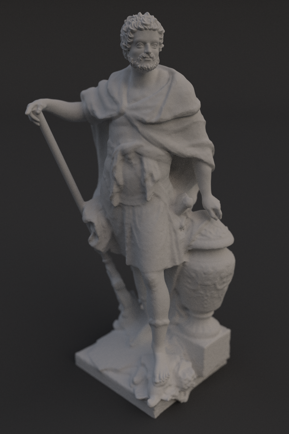
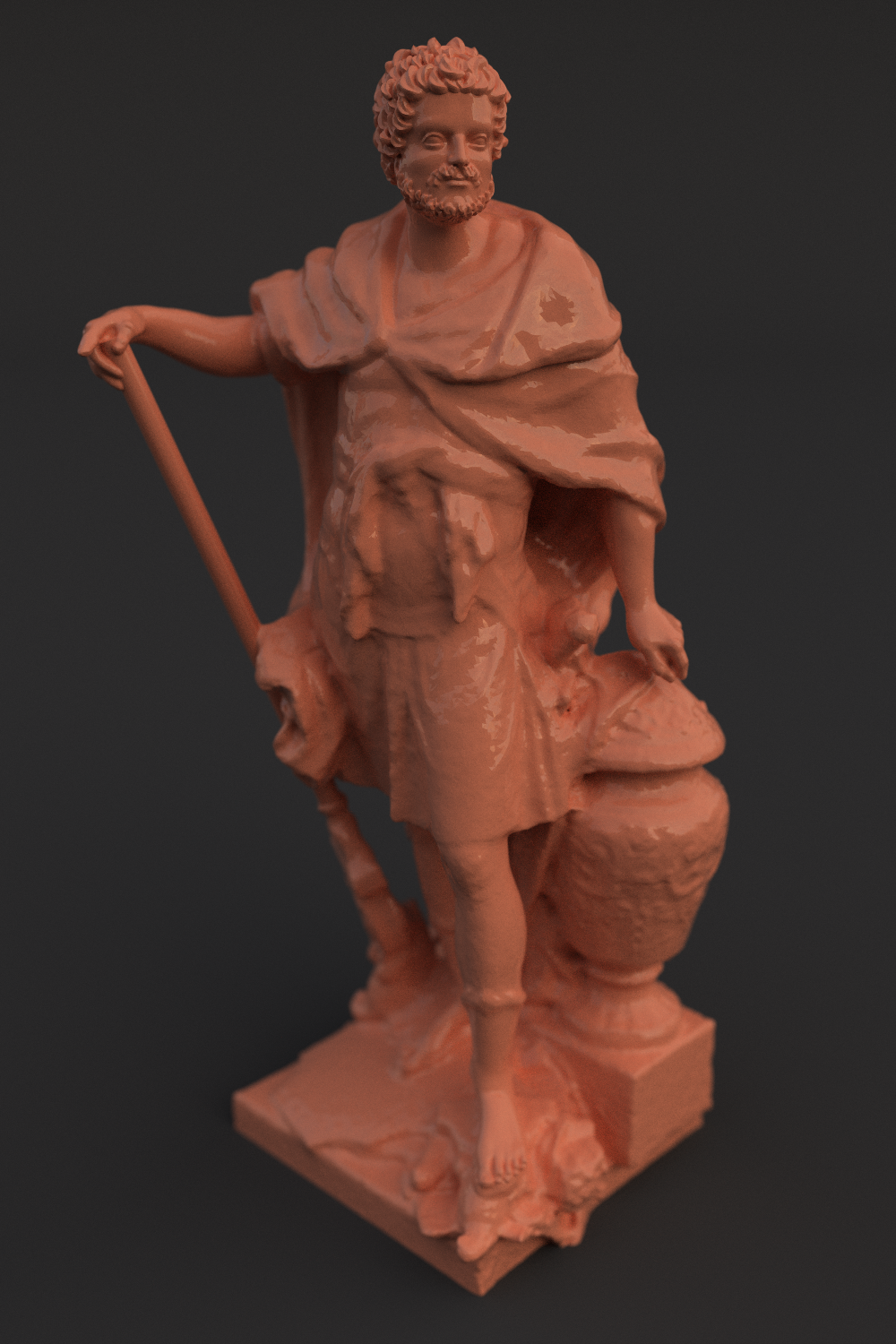
Path traced scan of a Hannibal sculpture by Sebastian Slodtz. Diffuse (left), glass coated diffuse (right). Model courtesy scan the world.
1. BVH Building & Ray Tracing
In order to path trace 3D models, I needed to build BVHs for those models and intersect those BVHs in a GPU kernel. The code to construct the BVH is written in C and compiled to Web Assembly (WASM) using Emscripten. Using WASM not only made the BVH building process significantly shorter, it also allowed me to operate on buffers that would be sent to the GPU similarly to how they would be read by the GPU, rather than using a DataView or typed array in JavaScript. The BVH was represented by two buffers: a flat array of internal and leaf nodes, and an array of primitives (triangles in this case). The memory layout for each looks like this:
1
2
3
4
5
6
7
8
9
10
11
12
13
14
15
16
17
18
2
3
4
5
6
7
8
9
10
11
12
13
14
15
16
17
18
struct BVH_Branch {
    float AABB_L_Lo[3];
    uint RightChildIndex;
    float AABB_L_Hi[3];
    uint PADDING0;
    float AABB_R_Lo[3];
    uint PADDING1;
    float AABB_R_Hi[3];
    uint PADDING2;
};

struct BVH_Leaf {
    uint primitiveStartIndex;
    uint primitiveEndIndex;
    uint PADDING0;
    uint LEAF_FLAG = 0; //set 0 to signal leaf
    uint PADDING1_12[12];
};
A parent node stores the bounding boxes of both its children; this is so that the intersection algorithm on the GPU does not have to read from two "random" memory addresses in order to pick which child nodes to traverse or skip. Additionally, each node assumes that its left child will be at the next index in the array, so it only stores an index for its right child. A leaf node points to a list of consecutive primitives in the array of primitives, and contains a flag (LEAF_FLAG) that distinguishes a branch node from a leaf node.
The ray-BVH intersection function, written in a WGSL-style syntax, looks something like this
1
2
3
4
5
6
7
8
9
10
11
12
13
14
15
16
17
18
19
20
21
22
23
24
25
26
27
28
29
30
31
32
33
34
35
36
37
38
39
40
41
42
43
44
45
46
47
48
49
50
51
52
53
54
55
56
57
58
59
60
61
62
63
64
65
66
67
68
69
70
71
72
73
74
75
76
77
78
79
80
81
2
3
4
5
6
7
8
9
10
11
12
13
14
15
16
17
18
19
20
21
22
23
24
25
26
27
28
29
30
31
32
33
34
35
36
37
38
39
40
41
42
43
44
45
46
47
48
49
50
51
52
53
54
55
56
57
58
59
60
61
62
63
64
65
66
67
68
69
70
71
72
73
74
75
76
77
78
79
80
81
@group(...) @binding(...) var<storage> bvh array<BVHNode>;

...

var<private> stack : array<u32, 64>;

fn intersect(o : vec3f, d : vec3f) -> RayHit {

    var closestDist = 1e30f;

    var stackPtr = 1u;
    var nodeIndex = 0u;
    var currentNode = 0u;

    //used to check if leaf node was just reached
    var newLeaf = false;

    //current primitive to check
    var primitiveLoIndex = 0;
    var primitiveHiIndex = 0;

    while (stackPointer != 0u) {
        var node : BVHNode = bvh[currentNode];

        //if this is a leaf node
        if (node.LEAF_FLAG == 0 && newLeaf) {
            newLeaf = false;

            primitiveLoIndex = node.primitiveStartIndex;
            primitiveHiIndex = node.primitiveEndIndex;
        }

        //if we have a primitive to intersect
        if (primitiveLoIndex < primitiveHiIndex) {
            //load and test triangle against o, d
            //using Moller-Trumbore
            ...

            if (HIT && newDist < closestDist) {
                closestDist = newDist;
            }
        } else {
            var leftDist  = AABBIntersect( node.leftAABB);
            var rightDist = AABBIntersect(node.rightAABB);

            //only traverse a child node if it is closer than closestDist
            var leftValid  = leftHit  > 0 && leftDist  <= closestDist;
            var rightValid = rightHit > 0 && rightDist <= closestDist;

            if (lValid && rValid) {
                //traverse the closer child first and
                //push the other index to the stack

                var furtherIndex = 0u;
                //note: left index is current index + 1
                var furtherIndex = 0;
                if (leftDist < rightDist) {
                    furtherIndex = node.rightChildIndedx;
                    currentNode  = currentNode + 1;
                } else {
                    furtherIndex = currentNode + 1;
                    currentNode  = node.rightChildIndex;
                }
                stack[stackPtr++] = furtherIndex;
            } else
            if (lValid) {
                //note: left index is current index + 1
                currentNode = currentNode + 1;
            } else
            if (rValid) {
                currentNode = node.rightChildIndex;
            } else {
                //traverse neither, go down the stack
                currentNode = stack[stackPtr--];
            }

            //flags that this may be a new leaf
            newLeaf = true;
        }
    }
}
The core of the function is a while loop that, with each iteration, either further searches the BVH for a leaf node, or tests against a triangle. The "..." in the primitive intersection portion of the function calculates the distance to the triangle and the normal using the Moller-Trumbore ray-triangle intersection algorith. There's really nothing new or innovative here, and there are probably further optimizations to be made. However, I found the performance to be good enough. I was too lazy to put together WebGPU QuerySets to test the time it took to intersect large models, but the path tracer does run at interactive frame rates for models with ~1M triangles on my laptop (Radeon RX 6700S).
One thing I did not get do here but would really like to do in the future is find a good way to store very large models in GPU buffers; currently, due to WebGPU limitations, the path tracer can only fit around 1M triangles into a storage buffer.
Early test of BVH ray tracing on the GPU. A ~1M model ray traced in real time on a laptop.
2. Wavefront Path Tracing
Wavefront path tracing works by splitting the traditional unrolled (loop-based/non-recursive) path tracing loop across multiple smaller and leaner GPU kernels. For example, consider a basic loop like the following:
1
2
3
4
5
6
7
8
9
10
11
12
13
14
15
16
17
18
19
20
21
22
2
3
4
5
6
7
8
9
10
11
12
13
14
15
16
17
18
19
20
21
22
//assuming position o, direction d are already defined

//t is the light accumulated across the path
var t = vec3f(0.);
var b = vec3f(1.);

for (var i = 0; i < MAX_BOUNCES; i++) {
    var normal : vec3f;
    var   dist :   f32;

    var bHit : bool = trace(o, d, &normal, &dist);

    //if path did not hit an object, accumulate sky color and break
    if (!bHit) {
        t += b * SKY_COLOR;
        break;
    }

    o = o + d * dist + normal * .001;

    b *= Sample_f_lambert(normal, &d);
}
What happens when we run this loop as-is with a workgroup size of 4 threads? The workgroup can only leave the for-loop once every thread has either hit MAX_BOUNCES or missed a surface. Consider the following scenario, where T represents calling trace() in an iteration and B represents the iteration that thread broke out of the loop.
| loop index: | 1 | 2 | 3 | 4 | 5 |
| thread 0: | T | T | T | T | B |
| thread 1: | T | B | - | - | - |
| thread 2: | B | - | - | - | - |
| thread 3: | T | B | - | - | - |
In this example, thread 0 bounced into a crevice and took 5 iterations to reach the sky light, while thread 2 did not hit a surface at all. Even though threads 1, 2, and 3 broke out of the loop relatively early, the workgroup was not able to leave the loop until thread 0 was finished. Thus we wasted 10 extra traces (3 from thread 1, 4 from thread 2, and 3 from thread 3). One of the goals of wavefront path tracing is to allow the loop to regenerate rays so that the execution of the trace() function across a workgroup runs across as many threads as possible. For example, if we change our code slightly:
1
2
3
4
5
6
7
8
9
10
11
12
13
14
15
16
17
18
19
20
21
22
23
24
25
26
27
28
29
30
2
3
4
5
6
7
8
9
10
11
12
13
14
15
16
17
18
19
20
21
22
23
24
25
26
27
28
29
30
//assuming position o, direction d are already defined

//t is the light accumulated across the path
var t = vec3f(0.);
var b = vec3f(1.);

var samples = 0;

for (var i = 0; i < MAX_BOUNCES; i++) {
    var normal : vec3f;
    var   dist :   f32;

    var bHit : bool = trace(o, d, &normal, &dist);

    //if path did not hit an object, accumulate sky color and break
    if (!bHit) {
        t += b * SKY_COLOR;
        samples++;

        regenerateCameraRay(&o, &d);
        b = vec3f(1.);
    } else {
        o = o + d * dist + normal * .001;

        b *= Sample_f_lambert(normal, &d);
    }
}

//safeguard to prevent NaN
var sumColor = samples == 0 ? vec3f(0.) : t / f32(samples);
Since we can regenerate rays inside the loop, we can ensure that no thread is sitting idle during a call to trace(). This adds some overhead, since now the branch "if(!bHit){...}" is larger and thus threads that do not take it will sit "idle" for longer; however, this is more than made up for by having more threads executing the significantly more expensive trace() function.
Wavefront path tracing as described in the paper goes much beyond this simple optimization: it actually splits the trace function, material evaluation, ray generation, and loop logic into seperate kernels which communicate through storage buffers. I chose to implement this, at least partially: the program executes four seperate kernels each iteration and communicates between them with queues and atomic operations. I won't go into much more detail, as most of this is described thoroughly in the paper. One thing to note is that my current implementation does not use ExecuteIndirect(), meaning it has to read the size of each queue back to the CPU multiple times a frame; switching to ExecuteIndirect would probably be one of the simplest yet most beneficial optimizations I could make in the future.
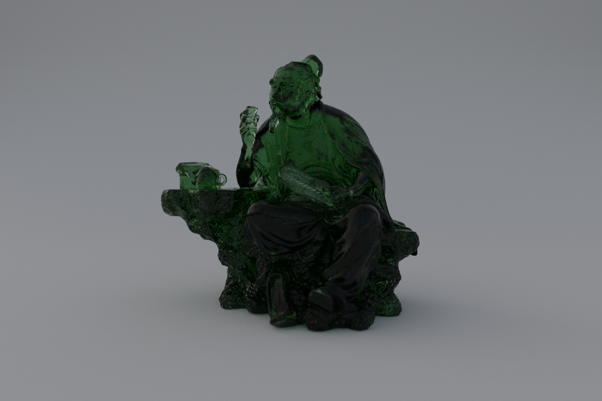
Figurine path traced with transmissive material. Model courtesy scan the world.
3. Image Based Lighting
It can be difficult setting up lighting that looks realistic. For this project, I decided to use an HDR image as a skylight. The one file in the entire source code not written by me is the C Program "hdrToFloats.cc" which is from this site. It reads a .HDR file and outputs a buffer of floats ready to be sent to the GPU. In the future, I could probably get away with sending the raw .HDR file to the GPU, then reconstructing the RGB value from the mantissas and shared exponent using a bitcast operation.
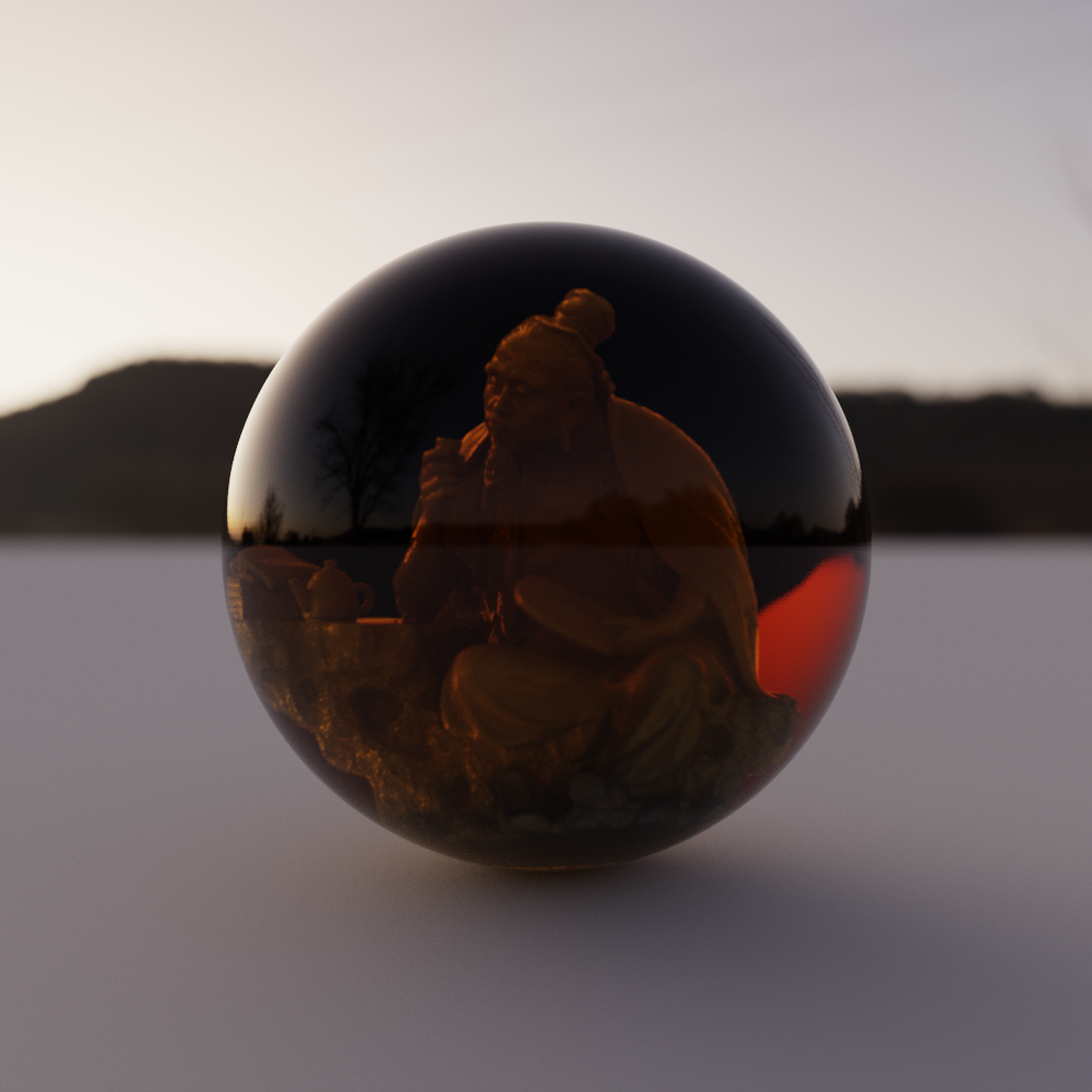
Path tracing example with Image Based Lighting.
4. Interface
The interface for interacting with the path tracer is broken into four seperate editor windows: "Meshes", which allows users to import .obj files and convert them to BVHs; "Objects", which allows the user to rotate, position, and change the materials and meshes of different objects; "Materials", which allows the user to edit properties of the materials applied to objects; and "Camera & Film", which allows the user to change the size of the render and the focal length and aperture of the camera.
The interface is one of my least favorite parts of the project, and I am hoping that in the future I could recreate a project similar to this one but with a much better interface. I would also like to re-implement wavefront path tracing and BVH ray tracing with a greater focus on performance.
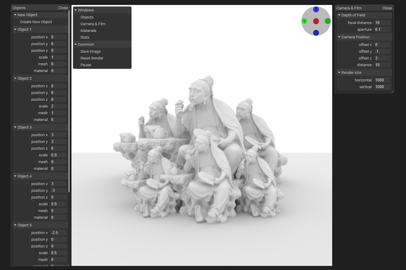
A screenshot of a work-in-progress editor interface.